


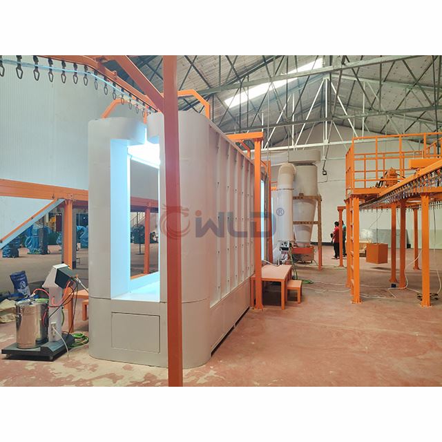
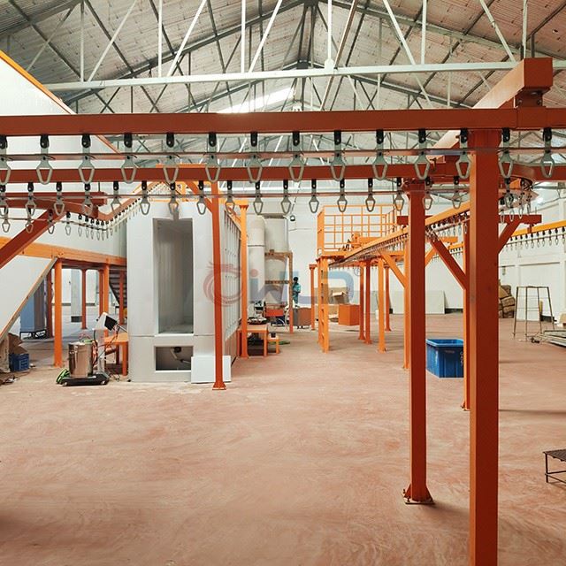
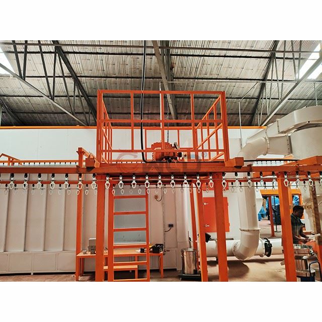
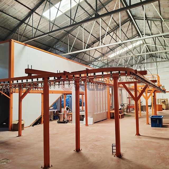
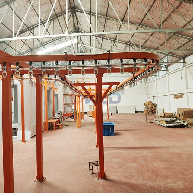
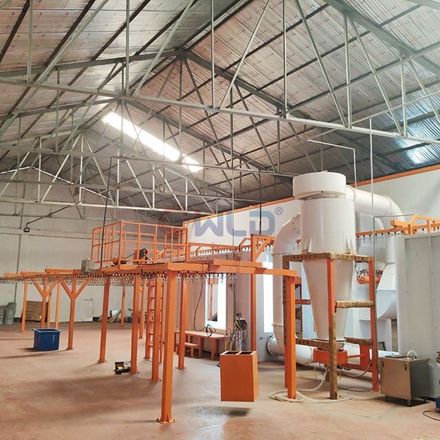

Electrostatic Automatic Powder Coating Line With Powder Recycling System
If you are interested in the electrostatic automatic powder coating line with powder recycling system, please be free to wholesale the quality and durable equipment made in China with our factory. We are one of the leading and professional spray paint booth manufacturers and suppliers in China. We are always at your service.
Curing Oven Introduction: The oven employs an overhead bridge-type design to optimize workshop space utilization. It is powered by a gas burner, and a fan circulates the air within the oven to the combustion chamber, thereby raising the internal temperature. This internal circulation heating configuration significantly enhances energy efficiency, ensures uniform temperature distribution across the oven, and improves product yield rates.
Waste gas collection hood: The waste gas collection hood is constructed from galvanized steel sheet, featuring one set of inlet and one set of outlet openings for the furnace.
Combustion chamber: The combustion chamber features an inner liner made of high-temperature-resistant stainless steel plates, with a 150 mm thick insulation layer, ensuring both durability and exceptional thermal insulation performance.
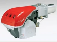
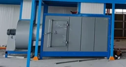

Combustion Chamber Appendix
|
insulating layer: |
T = 150 mm; bulk density: 120 kg/m³; inner panel: δ0.8 galvanized steel sheet; outer panel: δ0.6 colored steel sheet |
Rebar reinforcement treatment |
|
Combustor |
Lielu, 300,000 kcal (Italian brand) |
|
|
bordure |
Bending of δ1.5 galvanized steel sheet |
Powder coating treatment |
|
access hole |
Standard configuration: 1 set |
|
|
Heating method |
4-72-5C Hot Air Circulation |
|
|
Inner tank |
Stainless steel 304 |
weld |
furnace body attachment
|
Curing furnace: L = 21 m; operating temperature: 200 °C Curing furnace: L = 21 m; operating temperature: 200 °C |
||
|
Insulation board: 125 mm rock wool board |
Inner layer: δ0.8 galvanized steel sheet; outer layer: δ0.476 colored steel sheet; bulk density: 100 kg/m³ |
|
|
Heating: Hot air circulation |
Recirculation fan: 4-72-5C |
Quantity: 1 unit |
|
Air supply duct: δ1.2 galvanized steel sheet, bent |
||
|
Return air duct: δ1.2 galvanized steel sheet bent |
Insulation padding, 50 cm cotton board frame |
|
|
Chassis: 10# galvanized square tubing |
Surface treatment: powder coating |
|
|
Edge banding: δ1.5 galvanized steel sheet bending |
Surface treatment: powder coating |
|
|
Inside the cotton board joint: aluminum silicate |
High-temperature adhesive sealing |
|
|
Exhaust gas collection hood |
δ1.2 Galvanized steel sheet bending |
|
|
access door |
1 set |
|
|
Maintenance platform |
1 set of patterned flooring panels |
Equipped with a ladder |
|
Drying oven: L=21 m; temperature uncontrolled (approximately 120 °C) Drying oven: L=21 m; temperature uncontrolled (approximately 120 °C) |
||
|
Heating energy source (None) |
Solidified heat transfer (heat transfer via partition plates in inter-chamber galvanizing) |
|
|
Insulation board: 125 mm rock wool board |
Inner layer: δ0.8 galvanized steel sheet; outer layer: δ0.476 colored steel sheet; bulk density: 100 kg/m³ |
|
|
Dimensions: Inner diameter 600 mm |
||
|
Explosion-proof port |
1 set |
standard configuration |
Note: The equipment does not include water supply/drainage, air supply/extraction, power supply, or civil engineering works.
II. Powder coating room (filter-element type galvanized steel sheets)
Introduction to powder coating booth: Galvanized steel plate powder coating booth, constructed from galvanized steel sheets that are bent and then subjected to powder coating treatment; designed for cost-effectiveness and durability.
Filter element: Imported coated filter element with exceptional powder filtration performance, reducing the health risks posed by fine powders to humans.
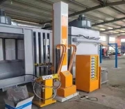
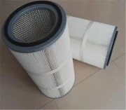
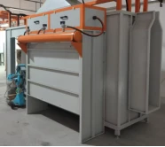
Appendix: Powder Spraying Room
|
Powder coating room: L6700 × W1220 × H2600; subject to the final approved design; Quantity: 2 units Powder coating room: L6700 × W1220 × H2600; subject to the final approved design; Quantity: 2 units |
||
|
Building panel materials: δ1.2 galvanized steel sheet, bent |
Powder coating treatment |
|
|
Base plate: δ1.5 galvanized steel sheet |
Powder coating treatment |
|
|
Frame: 5# square tubing |
Powder coating treatment |
|
|
Filter element: Laminated filter element (quick-release type) |
L=900 mm per unit |
Quantity: 8 in total |
|
Reverse blowing: pulse valve type |
The back-blowing time interval is adjustable. |
Default: 15s |
|
Counter-blowing configuration: explosion head |
made of aluminum |
|
|
Reverse-blowing bag: φ140 seamless pipe |
Powder coating treatment |
|
|
Artificial platform: patterned plate |
Frame: 5# square tubing |
Quantity: 2 sets |
|
Lighting: LED lamps |
Total: 6 sets |
|
|
Pressure Regulation: Pressure regulating valve |
With oil-water separation |
Quantity: 1 |
|
Manual powder spray gun |
Customer Selection |
|
III. Conveying System
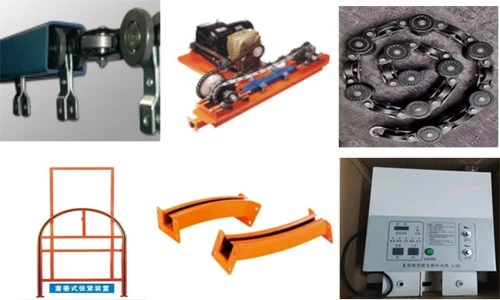
The conveying equipment primarily consists of an electric drive unit, a counterweight tensioning mechanism, chains, tracks, curved tracks, telescopic tracks, inspection tracks, supports, an electrical control system, and an automatic overload protection device.
The Type 250 heavy-duty suspended conveyor chain is employed, with a single-point lifting capacity of 100 kg; one set of electric drive units (Vmax ≈ 0–6 m/min) is installed. The tensioning device is equipped with a displacement limit protection switch to ensure smooth operation of the entire conveyor line. Emergency stop switches are installed along the entire conveyor line within its operating area, and the drive system incorporates both mechanical and electrical safety protections.
Chain track support frame: constructed from 100×100 mm carbon steel square tubing, finished with paint coating.
For areas subject to significant wear-such as elbows, lifting points, track elbows, and the track assembly of lifting mechanisms-carbiding treatment shall be applied to increase hardness in these regions, thereby enhancing wear resistance and extending service life.
Transportation Schedule
|
order number |
project |
specifications |
quantity |
remarks |
|
1 |
track |
QXT-150 |
Approximately 150 m |
Fit with track plate |
|
2 |
chain |
QXT-150 |
Approximately 150 m |
|
|
3 |
Elbow/Lift Assembly |
QXT-150 |
Formula 1 |
carbonization |
|
4 |
actuating device |
QXT-150 |
1 set |
4kw |
|
5 |
Tensioning device |
QXT-150 |
1 set |
Hammer-type |
|
6 |
Oil collection plate |
150# |
Approximately 1,000 tablets |
galvanized sheet |
|
7 |
Automatic fuel dispenser |
150# |
1 set |
|
|
8 |
Track post |
100*100 square channel steel |
6 m per strand |
Painting Treatment |
IV. Electrical Control Specifications
The entire equipment control system consists of the power distribution cabinet, the main control console, the auxiliary control cabinets, and the wiring, among other components;
Various temperature control systems employ digital display alarm instruments. The control cabinets and operation consoles are installed in appropriate on-site locations, with the cabinets and consoles positioned above cable trenches; the wiring between the consoles is connected via these cable trenches. The control system features start/stop operation and includes both audible and visual warning signals for both startup and shutdown phases, ensuring that no workpieces are present during startup, shutdown, or when operating under human-machine safety conditions. The equipment control cabinets comply with national standard modular designs, feature an electrostatic powder-coated exterior, and are equipped with lighting and maintenance sockets as well as cooling fans. Inside the cabinets, the wiring for AC, DC, high-voltage, and low-voltage circuits is color-coded in accordance with national standards.
The main circuit of the motor in the electronic control system employs conventional components-circuit breakers, contactors, and thermal relays-to provide protection against short circuits, overloads, and phase failures.
The temperature control system employs a digital temperature controller, utilizing a thermocouple as the temperature sensor to ensure high temperature measurement accuracy and stable control performance. The burner control system also utilizes this temperature controller, which features P-ID parameter self-tuning and PID automatic regulation capabilities. Through appropriate design measures in both the burner system and the temperature control circuitry, the system is equipped with PID regulation functionality, thereby enhancing its temperature control performance.
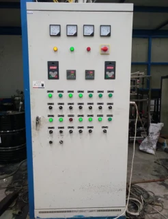
The electrical control cabinet features a rational layout, neatly organized internal components, clear labeling, and ample internal space. All critical components are sourced from renowned domestic and international manufacturers, with all domestically produced electrical components being high-quality products from nationally recognized leading manufacturers. The cabinet also employs energy-efficient products and ensures easy procurement for future maintenance.
ON/OFF switch type 1
Digital temperature controller: one unit per furnace is used to regulate the main temperature of the furnace.
Non-standard design of electrical control cabinet in GGD configuration.
Schematic diagram of the right electrical control box (reference image)
The main motor circuit of the electronic control system employs conventional components-circuit breakers, contactors, and thermal relays-to provide protection against short circuits, overloads, and phase failures. For motors with a rated power exceeding 7.5 kW, a Y-Δ starting method is adopted, with interlocking mechanisms implemented between the Y and Δ starting modes.
The electrical control cabinet features a well-organized layout, clean internal arrangement, and clear labeling. All critical components consist of high-quality products from renowned international brands, while domestic electrical components are premium products from nationally recognized leading manufacturers, incorporating energy-efficient solutions and ensuring easy procurement for future maintenance.
A control configuration utilizing a Mitsubishi touch screen and a Mitsubishi PLC is employed.
Key electrical components utilize internationally renowned brands such as Schneider and Omron.
Painted hardware treatment for the electrical control cabinet, ensuring an aesthetically pleasing and professional appearance.
The electrical control system primarily consists of a spray painting chamber, a drying oven, a high-temperature baking oven, and a conveyor chain control system.
Each motor operation control circuit is equipped with appropriate protective components, such as low-voltage circuit breakers and thermal relays, to provide short-circuit and overload protection for the motor. During normal operation, a green indicator light is illuminated; in the event of a fault, audible and visual alarms are activated. The primary electrical components of the control system consist of high-quality products from domestic and international manufacturers, as well as well-known brands from Sino-foreign joint ventures.
|
project |
brand |
|
frequency transformer |
Mitsubishi of Japan |
|
air switch |
Chint |
|
contactor |
Chint |
|
circuit breaker |
Chint |
|
thermal relay |
Chint |
|
Cable tray |
Taiwan Tiande |
|
auxiliary relay |
Omron of Japan |
|
thermostat |
Higashizaki |
|
voltmeter |
Chint |
|
push-button |
Schneider Electric Shanghai |
|
Locking mechanism |
Schneider Electric Shanghai |
|
pilot lamp |
Schneider Electric Shanghai |
|
buzzer |
KoreaKACON |
|
wire |
Guangzhou Pearl River |
|
touch screen |
Mitsubishi of Japan |
|
PLC |
Mitsubishi of Japan |
|
HIM (Human-Machine Interface) |
Taiwan Win |
Appendix (The components and brands listed herein are for reference purposes only; not all components are used in every individual project)
Hot Tags: electrostatic automatic powder coating line with powder recycling system, China, manufacturers, suppliers, factory, wholesale, made in China
You Might Also Like


Send Inquiry